 EN

What Makes Control Valve Essential For Modern Fluid Control
In an automated fluid system, a Control Valve is the device that turns a controller decision into a physical change in the process. A sensor may detect rising pressure, falling level, or a temperature shift; the controller can calculate a response, but the loop only affects the fluid when the valve moves. That is why a Control Valve is often treated as the final control element. It adjusts resistance to flow so the system can move toward its intended operating condition rather than simply report a deviation.
From an automation-control perspective, the practical question is not whether a Control Valve is important in isolation. It is whether the valve body, actuator, position feedback, control signal, and piping conditions work together. This distinction matters in water treatment, chemical handling, oil-related processes, and many other industrial lines where flow changes influence downstream operations.
A Control Valve connects measurement to process action
A modern loop normally has four linked jobs: measure a process value, compare it with a target, calculate a correction, and change the process. The Control Valve performs the last job. By changing the available flow passage, it can influence flow rate directly and can contribute to pressure, temperature, or liquid-level control depending on the loop design.
This is more than an on/off function. An isolation valve usually establishes a discrete open or closed state. A throttling Control Valve is expected to take intermediate positions repeatedly and predictably enough for the controller to make useful corrections. When demand, inlet conditions, or downstream resistance changes, the Control Valve provides the adjustable restriction that allows the loop to respond.
That role explains why valve selection cannot stop at nominal pipe size. A Control Valve that fits the line but does not match the required controllability, pressure drop, or actuator response can make a well-designed control strategy difficult to execute. In procurement conversations, defining the duty first generally reduces later clarification.
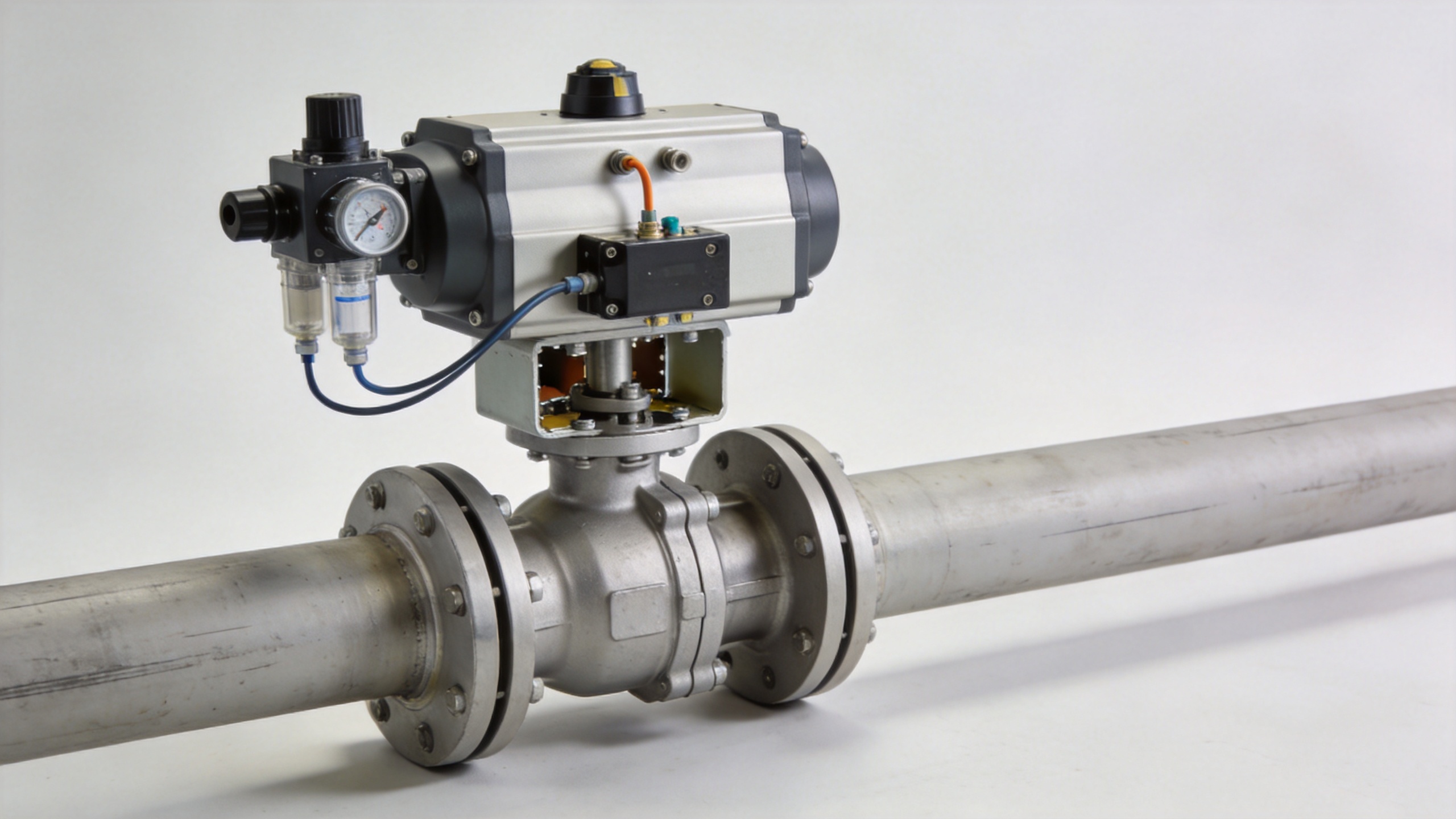
The valve body is only one part of the Control Valve
It is tempting to describe a Control Valve only by body style: globe, ball, butterfly, diaphragm, or another design. Body geometry matters because it affects flow path, shutoff approach, rangeability, pressure loss, and material options. Yet the Control Valve is a system component, not merely a body in a pipeline.
The actuator supplies movement. A pneumatic actuator, electric actuator, or hydraulic drive must generate suitable force or torque across the operating range. The positioner or signal connection translates the command signal into valve travel, while feedback helps the system know whether the requested position was achieved. In automated service, the Control Valve must also be considered with its fail action: the selected response to loss of air, power, or signal needs to suit the process review.
In other words, a Control Valve may be technically appropriate only when its body, trim, seals, actuator, and signal connection are evaluated together. A single pressure rating is useful, but its relationship to the medium, line conditions, and control objective is more useful.
Why modulating control improves fluid-system decisions
Fluid systems rarely operate at one unchanging point. Feed rates vary, tank levels move, temperatures drift, and process demand changes. A Control Valve gives the automation system a way to make gradual corrections instead of relying solely on manual intervention or repeated full-open/full-close cycling. Where the application needs modulation, the intended flow characteristic and usable travel range should be assessed rather than assumed.
For example, in a treatment line, a Control Valve may regulate the flow entering a stage so the downstream equipment receives a more stable condition. In a chemical process, the same principle may apply to a utility stream or a feed stream, but the compatibility of wetted materials and seals requires separate confirmation. The general function is familiar; the correct configuration is application-specific.
Modern controls can also coordinate a Control Valve with alarms, interlocks, variable-speed equipment, and supervisory systems. That integration does not make valve sizing or mechanical selection less important. It makes the consequences of a mismatched Control Valve more visible, because a signal command and the actual process response may no longer align as expected.
Where the auxiliary valve terms fit
A pressure compensated flow control valve is relevant when maintaining a more consistent flow despite pressure variation is central to the hydraulic task. It should not be treated as a universal substitute for every Control Valve. The expected pressure range, flow range, fluid cleanliness, circuit layout, and response requirements still determine whether that approach fits the system.
A cross hydraulic valve may appear in hydraulic circuit discussions where the architecture calls for a particular cross-flow or directional arrangement. The term alone does not establish suitability. As with any Control Valve decision, the circuit diagram, ports, relief strategy, load behavior, and required control outcome should be reviewed before a configuration is chosen.
These examples reinforce an important distinction: a keyword can identify a technical category, but it cannot replace operating data. The Control Valve choice should follow the process requirement, not the other way around.
Five questions that make Control Valve selection more reliable
- What is the fluid? Identify its composition, solids content, corrosiveness, viscosity, and cleanliness requirements where relevant.
- What must be controlled? State whether the loop primarily manages flow, pressure, temperature, level, or a related process variable.
- What are the operating limits? Record normal and expected minimum and maximum flow, pressure, and temperature, not only a single design point.
- How will the Control Valve be driven? Confirm available air, electrical supply, hydraulic power, signal type, feedback needs, and desired fail action.
- What does the installation require? Check connection style, installation orientation, available maintenance clearance, accessibility, and documentation requirements.
These questions make it easier to distinguish what is known from what still needs verification. They also help suppliers and project teams discuss a Control Valve configuration using the same technical language. For industrial valve and automation discussions, separating confirmed data from assumptions is more useful than promising a single valve type for every application.
Control Valve value comes from fit, not from a label
The essential value of a Control Valve is its ability to translate a control decision into controlled fluid behavior. Its importance grows as a process needs repeatable modulation, remote operation, feedback, or coordinated automation. Still, the correct result depends on fit: process medium, operating envelope, valve construction, actuator, signal path, safety review, and maintainability all matter.
Before specifying a Control Valve, assemble the fluid data, flow range, pressure and temperature conditions, connection details, control objective, and failure-state expectations. That information provides a sound starting point for comparing manual, pneumatic, electric, and other automated configurations. It also keeps the discussion focused on the conditions that determine whether a Control Valve can support the intended fluid-control task.
 Hot News