
 EN

Where To Apply Hydraulic Control Valve For High Force?
High-force motion is rarely just a cylinder-sizing question. In a press, lifting fixture, material-handling machine, water-control package, or process skid, a Hydraulic Control Valve determines when oil reaches an actuator, where it returns, and how the circuit behaves when the load changes. In practice, apply a Hydraulic Control Valve where fluid power has to move, stop, hold, limit, or sequence a heavily loaded cylinder or motor under defined operating conditions.
From an industrial valve application engineer’s perspective, start with the fluid, pressure, temperature, load, and control method before choosing a valve pattern. A high-force system may have ample cylinder area yet still behave poorly if the Hydraulic Control Valve, relief function, return path, and load-holding method were selected separately.
What Does a Hydraulic Control Valve Do in a High-Force Circuit?
A Hydraulic Control Valve routes, meters, blocks, or limits hydraulic fluid. Directional versions choose the path between a pump, tank, cylinder, or motor. Pressure-control functions manage pressure limits or sequencing. Flow-control functions influence actuator speed. Check or counterbalance arrangements can help manage reverse flow and suspended or overrunning loads. One installation can combine several functions, but each should be evaluated against the circuit rather than assumed from the valve’s name.
For high-force work, the central question is not “which valve is stronger?” It is whether the Hydraulic Control Valve can provide the required porting, flow path, pressure rating, response, and intended failure behavior while the actuator sees real load changes. If pressure, temperature, or load will vary, those changes belong in the selection review.
Applications Where High Force Makes Hydraulic Control Valuable
Pressing, clamping, and forming equipment
Hydraulic presses, clamps, crimping fixtures, and forming stations need force during a controlled portion of the stroke. A Hydraulic Control Valve can direct extension and retraction, while pressure-control elements set the circuit boundary and flow-control elements tune approach or return speed. In this application, distinguish a rapid low-load approach from the high-force work stroke. The valve arrangement needs to reflect both modes rather than treating the cycle as one constant demand.
Lifting, lowering, and load-holding machinery
Lift tables, hoists, movable platforms, and vertically oriented cylinders require particular care because gravity can drive motion. A Hydraulic Control Valve used only to change direction may not be enough to control a lowering load. Review whether the load can overrun, what holds position when the command is removed, and what pressure can develop at the actuator ports. A counterbalance or load-holding function may be appropriate depending on the engineered circuit and safety assessment.
Construction, transport, and material handling
Equipment that raises, tilts, steers, grips, or positions a heavy payload often uses a Hydraulic Control Valve to coordinate cylinders and motors. Examples include tipping bodies, handling attachments, compacting mechanisms, dock equipment, and purpose-built lifting fixtures. The selection must account for shock loads, duty cycle, hose routing, contamination control, and the operator’s required precision. A small valve body is not automatically a small-system choice; rated flow and pressure loss across the intended operating range matter.
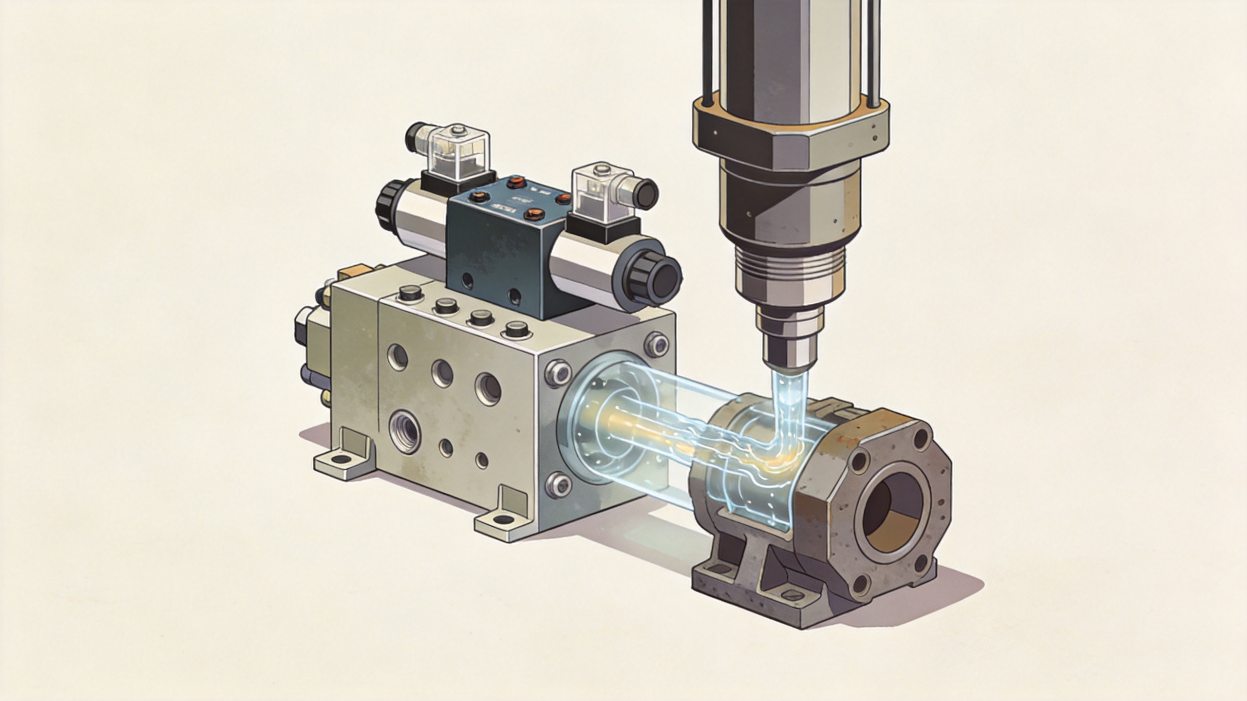
Water treatment, oil, and chemical process support
Industrial systems in water treatment, oil service, or chemical processing can use hydraulic actuation where high thrust is needed to move or position large mechanical elements. Here, a Hydraulic Control Valve is part of a larger package that should be checked for fluid compatibility, surrounding process conditions, access for service, and the connection between the power unit and the actuated device. Guangzhou Fols Valve Technology Co., Ltd. works in industrial-valve and automation contexts relevant to these sectors; final suitability still depends on the actual valve, actuator, and process data.
When a Solenoid Coil 24vdc Is a Useful Requirement
A solenoid coil 24vdc is commonly considered when a machine control system uses 24 VDC signals. In an electrohydraulic arrangement, the coil shifts or pilots a Hydraulic Control Valve so a controller, pushbutton, relay, or interlock can command motion. This does not by itself define the whole solution. Confirm the available supply voltage under load, connector and ingress requirements, coil duty rating, heat exposure, response expectation, manual override needs, and the valve’s spring-centered or detented state after power is removed.
For a high-force cylinder, document what the machine must do after an electrical interruption: stop, hold, return, or move to another defined safe condition. The answer is a circuit-design decision involving the Hydraulic Control Valve, actuator, load, and protective functions, not simply a coil selection.
A Field Checklist Before You Specify the Valve
- Force and pressure: State required push/pull force, bore and rod geometry, normal working pressure, expected peaks, and relief setting philosophy.
- Flow and speed: Calculate the flow required for extension, retraction, and any separate approach phase; then evaluate pressure drop through the Hydraulic Control Valve.
- Motion and ports: Identify the actuator type, number of ports, required directional states, center condition, and whether a motor or cylinder needs a different path.
- Load behavior: Note suspended, overrunning, side-loaded, or shock-loaded conditions and the method intended to limit unintended movement.
- Fluid and environment: Confirm hydraulic-fluid type, cleanliness target, temperature range, seal compatibility, corrosion exposure, and mounting space.
- Controls: Define manual, pilot, proportional, or 24 VDC solenoid control; list signals, connectors, diagnostics, and safe-state requirements.
- Service: Include filtration, access to coils and fittings, test points, replacement lead time, and documentation needs.
How to Compare Hydraulic Valve Suppliers
When reviewing hydraulic valve suppliers, compare more than a catalog pressure figure. Provide the same circuit brief to each candidate and ask for a clear response on port configuration, rated flow, permissible pressure, spool or poppet behavior, pilot requirements, coil specification, seal options, drawings, and test or documentation availability. Hydraulic valve suppliers can only evaluate suitability reliably when the operating conditions are complete.
A useful quotation package separates confirmed facts from items still requiring engineering review. For example, saying that a Hydraulic Control Valve is intended for a 24 VDC command is specific; claiming it will control a particular high-force load without the load, pressure, flow, and safety information is not. This distinction reduces revisions after procurement starts.
Make the Application Decision From the Whole Circuit
Apply a Hydraulic Control Valve where high force must be controlled with repeatable motion and defined circuit behavior: presses, clamps, lifting devices, mobile mechanisms, material-handling equipment, and process-support systems are common examples. The reliable path is to write down the conditions first, then match direction, pressure, flow, load holding, electrical control, and maintenance access. Do not start by asking whether one valve type is universally better; start by making the operating envelope clear.
 Hot News