 EN

Where To Apply Control Valve For Precision Flow Modulation?
A Control Valve is applied where a process needs continuous correction, not merely an open-or-closed flow path. It changes flow area in response to a controller signal, allowing a loop to hold a flow, level, pressure, temperature, or ratio near its intended setpoint. The practical selection question is therefore: where does changing flow produce a useful and measurable process response?
For precision work, a Control Valve must be evaluated as part of a loop that includes the process, transmitter, controller, valve body, actuator, and position feedback. A suitable valve cannot compensate for poor process data, wrong sensing location, or an unstable control strategy. Start with the service objective and operating envelope before choosing hardware.
Use a Control Valve When Flow Must Be Adjusted Continuously
A Control Valve fits a duty when the process requires intermediate positions rather than simple isolation. Typical locations include the following:
- Water-treatment dosing and dilution: a Control Valve adjusts chemical, make-up-water, or recirculation flow as the measured process condition changes.
- Tank and basin level loops: an inlet or outlet Control Valve balances changing inflow and outflow to maintain level without repeated on/off cycling.
- Heat-transfer circuits: a Control Valve regulates steam, hot water, cooling water, or thermal-fluid flow to influence a measured temperature.
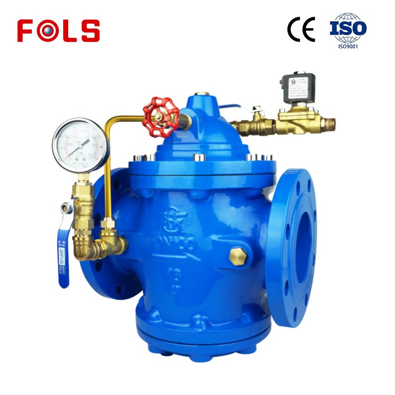
- Pressure-control lines: a Control Valve throttles supply, recycle, bypass, or vent flow when that action is the chosen way to manage pressure.
- Blending and ratio service: a Control Valve changes one stream in relation to another when the process uses flow measurement and control logic.
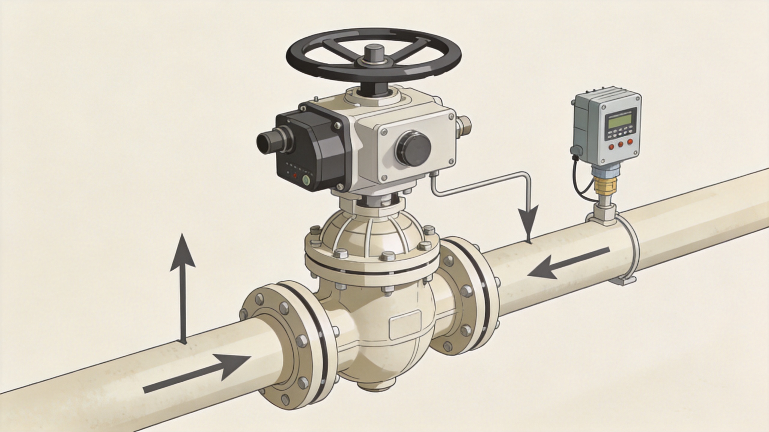
These applications occur in industrial water treatment, chemical lines, oil-related utility systems, and other variable-demand pipelines. A steady line that only needs isolation may need a shutoff valve instead. More accurately, apply a Control Valve only where the control loop benefits from gradual correction.
Place the Control Valve Around the Actual Control Objective
The location of a Control Valve follows the process objective, not a generic inlet-or-outlet rule. A vessel inlet may be the manipulated point for level control, while an outlet valve can be more suitable where downstream demand and pressure behavior support that arrangement. Review available differential pressure, pump limits, and the consequences of the valve's fail position.
For exchanger duty, the Control Valve should be installed in the stream whose flow actually drives the measured temperature. For a recycle line, confirm that modulation will not create an unwanted minimum-flow or deadhead condition. Drawing the loop and marking the measurement point, manipulated flow, and disturbance is a useful early check.
Size for the Entire Operating Range
Precision suffers when a Control Valve is oversized or lacks capacity. An oversized valve can spend normal operation close to the seat, where a small movement changes flow too sharply. A valve with too little capacity can remain close to full travel and have limited adjustment authority. Sizing should use minimum, normal, and maximum flow together with inlet and outlet pressure for each material operating case.
Do not assume line size equals valve size. The selected Control Valve should have enough capacity at peak demand while retaining controllable travel at normal and low demand. If liquid pressure drop is high, review flashing and cavitation conditions. Noise, vibration, and trim damage can result when the local pressure behavior is ignored.
Match Flow Characteristic to Installed Conditions
A Control Valve has an inherent relationship between travel and capacity, but pipeline resistance changes the installed relationship. Quick-opening, linear, and equal-percentage characteristics are commonly considered. Linear behavior can be appropriate where the pressure relationship remains comparatively stable. Equal-percentage behavior is often evaluated where the required flow range is broad and the system pressure distribution changes with load.
This is a decision for the actual loop, not a general rule for every Control Valve. Record the expected pressure drop across the valve at low, normal, and maximum demand. The resulting travel range is more informative than a valve type name alone.
Review the Valve Body and Actuation Together
The Control Valve body influences pressure rating, material suitability, end connection, flow path, and trim behavior. Confirm medium composition, temperature, viscosity, solids, corrosion concern, and shutoff requirement. In hydraulic service, the hydraulic valve body also requires review against circuit pressure, cleanliness, leakage route, response need, and available control method.
A linear motor actuator may be considered where the selected design needs electrically driven linear travel. Check stroke, stem force, speed, feedback, power supply, environmental conditions, and desired action on loss of power. A linear motor actuator can provide the selected motion, but it does not correct poor Control Valve sizing or an unsuitable trim. Likewise, a suitable hydraulic valve body must still match the circuit duty.
Specify Fail State and Commission the Loop
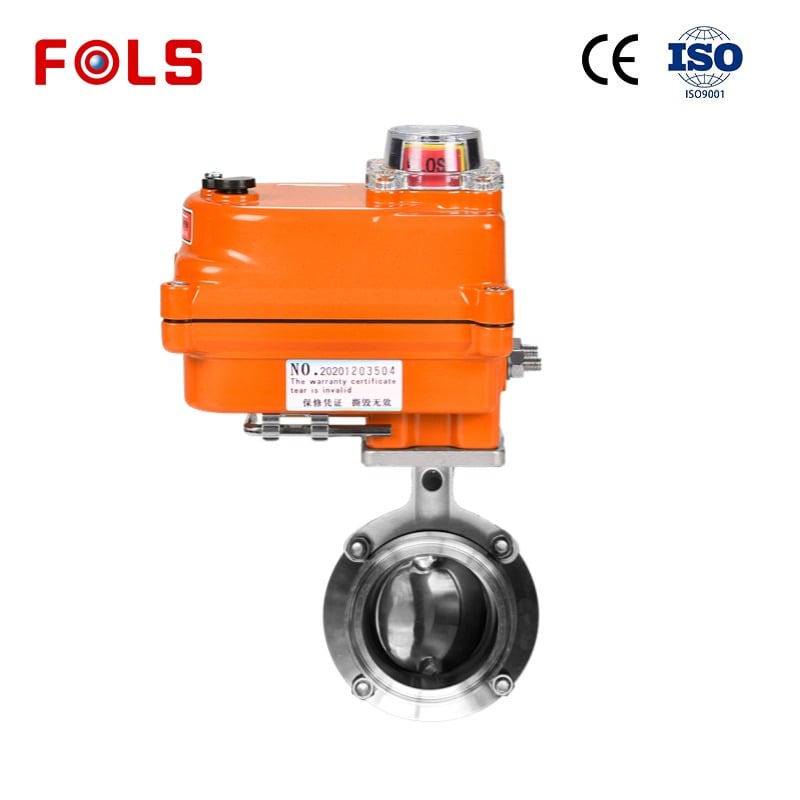
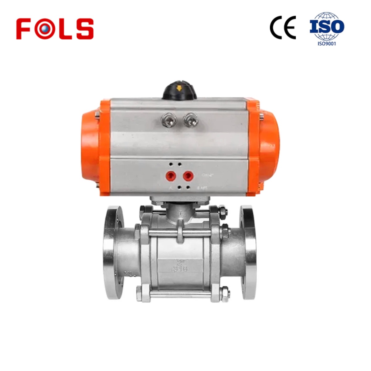
Actuation is part of the Control Valve decision. Pneumatic operation can fit sites with suitable air supply and a required spring-return action. Electric operation can suit other automation layouts. Choose fail-open, fail-closed, or fail-in-place according to process consequences, then verify controller output direction, actuator action, feedback scaling, and positioner calibration.
During commissioning, test the Control Valve at low and normal demand. Confirm travel direction, response, leakage expectation, signal calibration, vibration, and noise. If the loop hunts, the cause may be valve authority, but it may also be controller tuning, sensor placement, process delay, or upstream pressure variation.
Application Data to Prepare Before Selection
- Identify the controlled variable and the required response.
- Provide minimum, normal, and maximum flow with inlet and outlet pressure.
- Describe medium, temperature, solids, vapor-pressure considerations, and materials concerns.
- State connection, control signal, actuator preference, and required fail action.
- Request capacity, travel, pressure-drop, and liquid-service checks for the proposed Control Valve.
Guangzhou Fols Valve Technology Co., Ltd. supports industrial valve and automation discussions for applications including water treatment, oil, and chemical industries. With a complete operating-data sheet, a Control Valve configuration can be discussed on the basis of actual conditions rather than a generic recommendation.
Conclusion
Apply a Control Valve wherever controlled flow is the deliberate way to manage a changing process condition: dosing, level, thermal duty, pressure management, blending, and variable-demand recirculation are common examples. For reliable precision flow modulation, evaluate the whole loop—process objective, installed pressure drop, sizing range, valve body, trim, actuator, fail state, and commissioning plan.
 Hot News